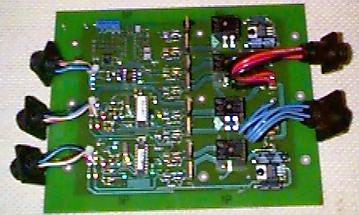

This is an enlarged picture of the first prototype Dual Processor Ignition Controller. Click on the thumbnails below to see enlarged photos of the test setup. If you're interested in an article published in Contact Magazine on Knock detection click on page1 or page2
| Dual Processor Ignition | |
|---|---|
 |
 |
| Click thumbnail for 1200x800 images | |
After the dual ignition was completed there came the requirement to have fuel injection for the HONDA VTEC engines. The Engine turns up to 6600RPM and that's much too fast for a propellor so a toothed belt reduction drive is connected to the crankshaft at the flywheel end. This means the stock Honda ignition/injection system along with the distributor won't fit. Also, the distributor is a weak spot in an engine so a waste spark multiple coil arrangement is much more effective. A Ford coil was chosen and this required a CD (Capacitive Discharge) ignition. First a prototype of the ignition control circuitry was designed and tested. After several refinements with a custom inductor, the target 80mJ of energy was ready to be dumped into the ignition coil.
Next, the Philips 80C592 processor with embedded CAN controller was chosen to be the micro-processor of the ignition/injection controller and a new circuit board was designed. This board had to use the existing case, brackets and connectors to make it possible to upgrade existing customers without requiring major wiring harness changes. Using as much as possible from the dual ignition product also resulted in lower inventory costs for Firewall Forward.
The controller uses the CAN bus to broadcast engine information so each controller has an address representing Engine 1 or 2. A special node at the aircraft or Hovercraft instrument panel will allow access to either engines' parameters with just the touch of a button. The breadboard protype is shown in the photo below. Note we're using the Lawicel C505C-BBE ( www.lawicel.com ) and the 8051 TASKING ( www.tasking.com ) C compiler to develop the software.
For development and diagnostics we use a PPCAN connected to the parallel port of a WIN-95 or WIN-98 PC. The PPCAN receives all CAN messages and a Delphi Application called Dashboard interprets the data and, using ActiveX controls, creates an animated Instrument Panel. Clicking on some of the gauges brings up a dialog of engine parameters that can be modified and then updated via the CAN bus into the EEROM inside the controller.
| CD Ignition/Injection c/d CAN interface | |
|---|---|
 |
 |
| Click thumbnail for 800x600 images | |
And finally, where it all comes together: