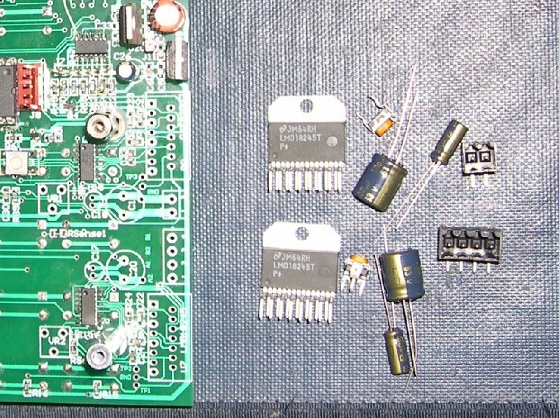
Below is the kit of parts needed for adding the Micro-Stepping hardware drivers. (as of 13May08 I've added assembly sequencing instructions.) It's easiest to install the kit before the key buttons are soldered in on the top side of the board. If you are retrofitting an existing board the plastic button extensions will be in the way so it's best to pop off the ones near the solder connections otherwise you'll probably bump into them with the soldering iron and create melted deformations.
Not really a lot there. Digikey prices as of April 2008.
| 2 | LMD18245T Driver | 13.04 * 2 = $26.08 |
| 2 | 20K trim pots but really fixed resistors are better. | 0.35 * 2 = $0.70 |
| 2 | 1uFd 63V cap | 0.24 * 2 = $0.48 |
| 2 | 100uF 63V cap | 0.44 * 2 = $0.88 |
| 1 | Optional 4 pin connector for stepper motor | 1.27 |
| 1 | Optional 2 pin connector for stepper motor power | 0.62 |
Best way to install the two LMD18245s is to screw a heatsink or thick flat bar to the LM7805 regulator and the two LMD18245s. This way the devices are held in the position they will be when finally assembled into a box. Otherwise, later you may stress the leads when bolting it in place if the devices have been soldered slightly crooked.
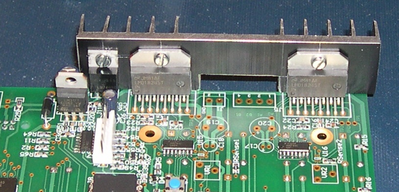
There's no reason to install the LMD18245s first. In fact it's probably easier to do the trim pots and capacitors (in that order) first. I've done it this way so the caps don't obscure the LMD18245s.
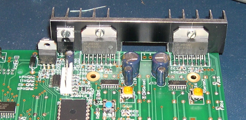
Now here's a picture with everything installed. I use connectors directly on the board because I'm swapping all sorts of ELS prototypes around. If you're mounting the ELS into a box that has connectors for the motor and power at the back then you can just run wires from those connectors directly to the circuit board.
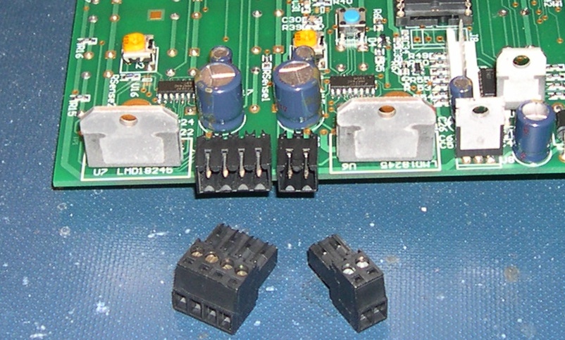
The two connectors installed on the board.
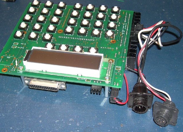
The back panel area with larger AMP CPC connectors. The one with the female sockets connects to the stepper motor while the one with the pins connects to +12V and +44V. (The connector supplying power is always a socket while the connector accepting power in is a plug.)
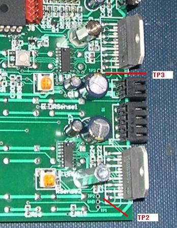
Next it's time to set the Micro-Stepper current limit. The two trim pots are adjusted to a specific resistance which can be measured at the TP2 and TP3 relative to GND.
From the LMD18245 data sheet:
CS OUT current sense resister
(DAC_REF x [MX4..MX0]/16) / (250E-6 x A) = RSenseX
Or if terms are reduced:
TPx = 18.75K / Motor Coil Amps
TPx = 18.75K for 1 Amps
TPx = 9.375K for 2 Amps
TPx = 6.8K for 2.75A (RHT23-260 Oz Motors)
TPx = 6.25K for 3 Amps
I used an Ohmmeter to measure between TP2 and GND and turned the bottom trim pot until the required resistance was displayed; in my case I needed 6.8K. I did the same with TP3 and GND.
And then I had to try it out.
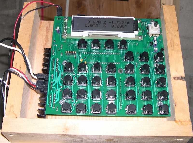
Couldn't get the motor to turn initially. Figured I had a serious problem. Then I discovered I hadn't plugged in the stepper motor. Remember not to plug in or unplug the stepper motor while power is applied to the ELS. After that it worked perfectly. I set the idle current timeout to 10 seconds and sure enough, after 10 seconds, I could twist the motor by hand with only a little bit of force. The idle current does hold the current micro-step position so going into idle doesn't mean that the mechanical position is lost.
The heatsink is a tad small if a motor requiring 3 amps is used. However, a small CPU fan aimed at the heatsink lowered the temperature really well.
Here's a link to a page describing the LMD18245 Direction Change Bug and Fix.